
Skip to content
A tracked excavator digging out ground on a residential building site

Groundworks contractors in Hampshire

Site clearance, bulk excavation, footings, drainage and structural retaining walls, dug and built by our own teams across Portsmouth, Southampton and Winchester.

Below ground

Footings, Foundations & Drainage

This is the part of a job nobody photographs and every cheap quote shortens. Clearance, the reduced dig, the sub-base, the concrete and the water all get specified before we price the work, so you can see exactly what is going into the ground.

Site clearance and strip out

We start by taking the site back to something we can measure. Vegetation and root systems are grubbed out rather than buried, old concrete, hardcore and slabs are broken out with a breaker on the machine, and the topsoil is stripped off in one pass so the reduced dig starts from clean ground.

Topsoil strip
Typically 150 to 300 mm, deeper where there is root activity or made ground
Obstructions
Old bases, tree stumps, redundant drainage and buried rubble removed, not covered over
Services
Cable avoidance scan and hand dig around anything live before the machine goes in
Bulk excavation and the reduced dig

Bulk excavation is dug to a set formation level rather than by eye, then the base is proof rolled to find any soft spots before stone goes down. Sub-base is laid and compacted in layers, never tipped in one lift and rolled once. A single 250 mm dump of stone compacts on the top 75 mm and stays loose underneath, which is where sunken paving comes from two winters later.

Compaction
Type 1 laid in 100 to 150 mm layers, each layer compacted before the next
Sub-base depth
150 mm for foot traffic and patios, 200 to 250 mm for a car drive, more for vehicles over 3.5 tonnes
Separation
Woven geotextile between subgrade and stone on clay or soft ground, so the two do not mix
Levels
Set out from a fixed datum with a laser level, falls designed in at formation stage

Footings and foundations

Footings for garden rooms, extensions, garden walls and outbuildings are dug to a depth that suits the ground, not to a habit. Hampshire has plenty of shrinkable clay and plenty of mature trees, and both push the required depth down. Trenches are dug square, the base is cleaned off, and the pour is inspected before it happens where building control is involved.

Strip footing
Commonly 450 to 600 mm wide, 600 mm minimum depth on firm ground
Clay and trees
900 mm and deeper where shrinkable clay or nearby root influence applies
Concrete
GEN3 or C25/30 as the design requires, poured in one continuous operation
Reinforcement
A142 or A252 mesh, or bar to a specified schedule, on spacers rather than pulled up by hand
Sign off
Trench inspected by building control before pouring where the work is notifiable

Drainage, soakaways and surface water

A new drive or patio is a new hard surface, and the water it sheds has to go somewhere legal. We work out where it goes before the surface is priced. That usually means a soakaway sized from a percolation test, a channel drain across a threshold, or a connection to an existing surface water run, and it never means running rainwater into a foul drain.

Soakaway sizing
Sized from a BRE Digest 365 percolation test and the contributing area, using crates or clean 40 mm stone wrapped in geotextile
Position
At least 5 metres from a building and clear of foundations and boundaries
Falls
1:80 minimum on 110 mm foul, 1:60 to 1:40 on surface water and channel outlets
Bedding
Pipework bedded and surrounded in 10 mm pea shingle, not laid straight onto spoil
Access
Inspection chambers at junctions and changes of direction, silt trap where a drive discharges
Permeable options
Permeable block paving or resin over an open graded sub-base where a soakaway is not viable

If a quote you are comparing does not say how deep the dig is, what the sub-base is, or where the water goes, those three things are the difference in price. Ours are written into the quotation in plain figures.

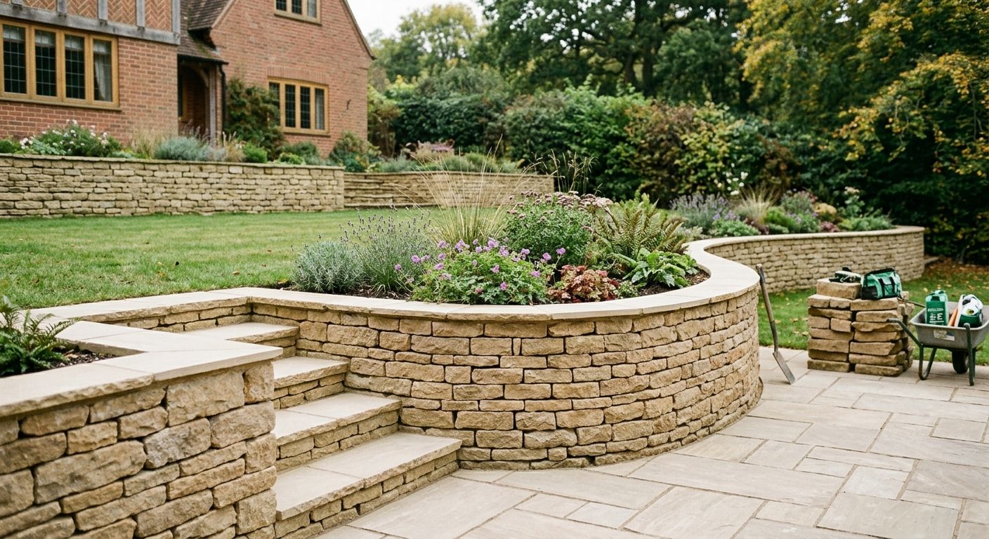
A curved natural stone retaining wall with steps up to a raised lawn

A retaining wall is a structure, not a decorative edge. It is holding back soil that gets heavier every time it rains.

Retaining Walls & Garden Masonry

Sloping Hampshire plots usually need a level to be won back before anything else can happen. We build the wall that does it, from a sleeper edge holding a raised bed to a reinforced concrete structure retaining a driveway.

Structural retaining walls

Reinforced concrete blockwork or a poured concrete stem on a mass concrete footing, used where the retained height, a driveway load or a neighbouring boundary makes the wall a structural element rather than a garden feature.

  • 215 mm dense blockwork, cores filled with concrete
  • Vertical starter bars cast into the footing
  • Faced in brick, render or stone afterwards

Sleeper walls

Treated softwood or hardwood sleepers on a concrete strip, tied back to steel posts set in concrete rather than simply stacked and screwed. Right for terracing, raised beds and low level changes, and quicker to build than masonry.

  • Steel or timber posts concreted below ground
  • Damp proof membrane on the retained face
  • Through bolted, not nailed

Brickwork and garden masonry

Boundary walls, piers, planters, steps and the facing skin on a retaining structure. Laid on a proper footing with the right mortar for the brick, so it does not spall in the first hard frost or crack across a long run.

  • Engineering brick below damp proof course
  • Movement joints on long runs
  • Coping or creasing course to shed water

Concrete and reinforcement

Retained soil pushes sideways, and that push increases with the square of the height. The footing and the steel are what resist it, so both are sized to the retained height and the ground behind rather than copied from the last job.

Footing
Mass concrete strip, commonly one third to one half of the retained height in width, minimum 450 mm below finished ground
Concrete
C25/30 or better for footings and filled cores, poured against clean, cleared trench faces
Steel
Vertical starter bars cast into the footing at designed centres, lapped into the wall, mesh in the base where the design calls for it
Design
Anything retaining much above 1 metre, carrying a vehicle load or sitting on a boundary is built to structural calculations, not to eye

Drainage behind the wall

Most failed retaining walls in this county did not fail because the blockwork was weak. They failed because water was allowed to build up behind them. Saturated clay pushes far harder than dry soil, so the water is given a route out from the day the wall goes up.

Land drain
100 mm perforated pipe at the base of the retained face, laid to a fall with a real outfall, not a dead end
Backfill
Clean 20 to 40 mm free draining stone against the wall, wrapped in geotextile so silt does not blind it
Weep holes
Through the lowest course at roughly 1 metre centres where a positive drain is not practical
Tanking
Waterproof membrane on the retained face, so ground water is not sitting against the masonry
Top of wall
Coping and surface falls take rainwater away from the back of the wall rather than into it

Retaining walls near a boundary can involve the Party Wall etc. Act 1996, and walls above a certain height beside a highway or a public footpath can need planning consent. We flag both at survey stage rather than after the footing is poured.

Not sure what your ground needs?

We will walk the plot, check the levels and tell you what has to come out before anything goes in. The visit and the written quotation both cost nothing.

Get a free quote